Since arriving at Jaaga I have been refamiliarising with simple electronics along with Agnese. Today we set up a simple circuit to drive a DC motor back and forth. We googled and found an online guide from a physical computing course at New York University, which was really helpful, and you should definitely check it out if you want to build this circuit.
It's pretty cool how much easier it is nowadays to find very friendly guides for beginners. In particular I like how they use a standardised Arduino graphic instead of dry schematics, which are great for being concise but offputting to the uninitiated.


The pushbutton on the top left of the breadboard is just there to change the polarity, i.e. the direction of the motor. It's essentially seperate from the rest of the circuit so we can ignore it and look to the rest.
The H-Bridge (the chip in the middle) looks a little scary to begin, especially when you first glance the graphic associated with it (below). But once you take the time to look over what each leg actually does, then you start to get a bit more comfortable.
The H-Bridge's job is to allow a motor which requires a high load (i.e. 5-15V) to be controlled by a control signal (i.e. the Arduino standard 5V). In this case the motor we are using accepts 5V but we're going to set up a circuit that will allow the use of more powerful motors, so that we can just switch the 5V for a 10 or 12V motor later... hence the need for the H-Bridge.
So since the H-Bridge just has to translate 5V control signals to 5-15V motor signals, what ins and outs might it need? You might expect one leg to go to the external 5-15V power source, one to ground, one to +5V, two to the motor, and one control signal to the Arduino.
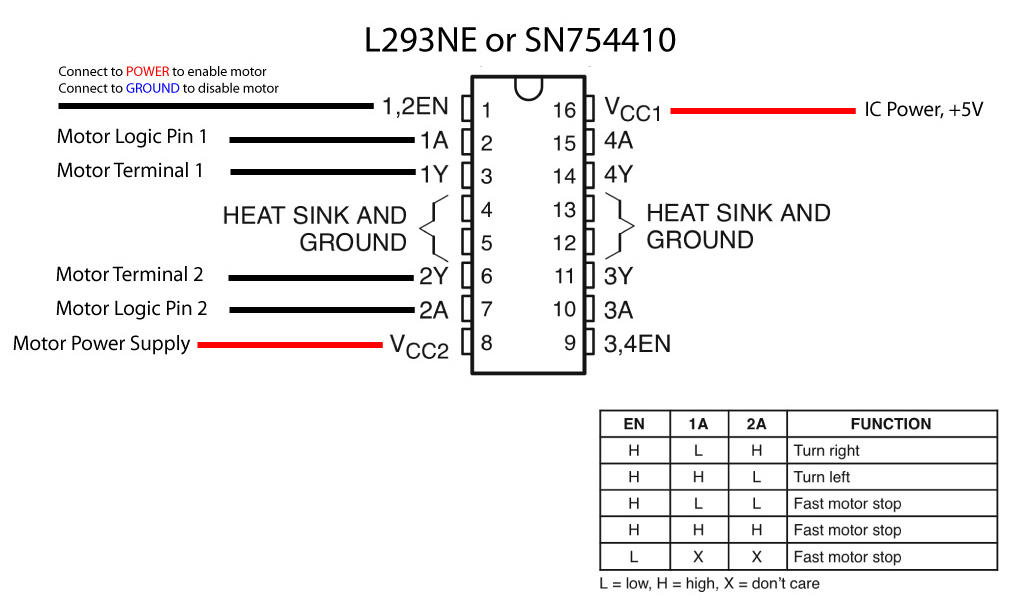
As the diagram shows, in reality things are a little different. The two that go to the motor are there - marked as 'Motor Terminal 1' and 'Motor Terminal 2'. The one that goes to the power supply is there too, marked 'VCC2'. But there are four legs that go to ground! This is according to the schematic and also the imagery in the guide. I don't know why yet, but that's OK - four it is.
The next odd thing is that we have not one but THREE control signals - i.e. legs that go to the Arduino's digital out pins - which are pins 1, 2 and 7 above. The reason is that in order to turn the motor one way you use the two 'Motor Logic Pins' and send HIGH to one and LOW to the other. When you want to reverse the motor, send the opposite - LOW to one and HIGH to the other.
The third control pin, (pin 1 in the diagram), is an enable switch. If it receives HIGH the motor will work, otherwise it will not. So you can connect it to a constant +5V or set it programmatically in the microcontroller code. It functions as a programmatic on/off switch or safety-off, i.e. like the big red buttons on heavy machinery.
And the pins that aren't connected to anything on the right-hand side of the H-Bridge? The H-Bridge can control two motors at once if you want, just mirror the pin setup you have on the left to the right.
Fun, geeky stuff. We'll pick up a more powerful motor to play with later today. Here's the final result for today: