I've been spending a lot of time today trying to figure out how best to connect the Servo motor we bought the other day. Unfortunately there isn't a NYU phys comp tutorial on driving servo motors with high voltages, which would have been ideal. I've had to learn a few new things, from a mixture of sources, and I'll pull the results together here.
The difference between standard geared motors and servo motors
So the first thing to understand is that a geared DC motor like the ones we used in the last couple of posts is quite dumb. It is directly controlled by the DC current you supply it via it's two inputs. You can only really tell it to start or stop. That's it.
You can vary the speed using PWM - but PWM is a kind of microcontroller 'hack' in a sense. What's really happening there is that you are very quickly turning it on and off, and varying the delay between those on and off commands. The motor itself doesn't have any control in that process - it just spins when it receives voltage in one of it's inputs.
If you wanted to be able to tell the motor to turn to a specific angle, you'd have to attach a sensor (i.e. a potentiometer) to the shaft. This could report the current angle of the shaft back to the microcontroller. You could use this information to figure out when to switch off the current to the motor to have it arrive at your desired destination on time.
And this is exactly what a servo motor does, except rather than reporting the position back to the microcontroller and you having to work it out, you just send the position you would like it to achieve, and it does all the working out for you. For this reason, unlike the standard geared DC motors, it has three inputs - one for ground, one for V+, and one to send your control signal.
When to use a H-Bridge and when to use a TIP120?
Tobias, and my Physical Computing book all seem to suggest I need a TIP120, not an L293 H-Bridge (which is what I used when connecting the motors in the previous posts). The question is, why?
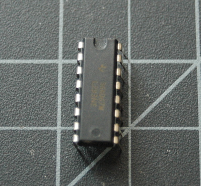
First off, what is a H-Bridge? And what is a TIP120? Going back to the beginning of the chapter (page 97), I get a brief explanation that of what a relay is and what a transistor is. It explains that a relay is an electromagnet that flicks a switch for you whenever you send a control current to it (i.e. it's a switch that doesn't need to be flicked by a person, you can flick it automatically in your microcontroller code). It then just says that a transistor does the same thing but doesn't have any moving parts, and so is quicker - but will only work with DC.
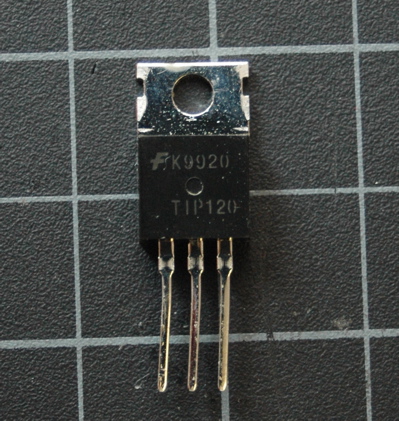
With some googling I find that the TIP120 and the L293 have something in common. The L293 H-Bridge contains transistors, and the TIP120 is a transistor. So it seems that driving powerful loads is all about transistors - using a control current to switch on and off a powerful current.
So this is the information I need to really make it make sense. Both components only allow you to switch higher-load circuits on or off. A standard geared DC motor is spun one way or another by alternating the direction of DC current through it's two connections. This is what an L293 H-Bridge is useful for, as it gives you two output legs to the motor, through which you can send HIGH to one and LOW to the other and vice versa.
However a servo motor only requires a a high voltage to give it some power to work with. The control signal can then be used as an enable pin, and then instead of blindly increasing and decreasing speed through PWM, you vary the speed and direction by using a second control signal that goes straight to the motor. The motor does the dirty work for you, and as a result you get a direct correlation between the value you send it and the location the shaft turns to - no wonder they are more expensive. So for this, a single transistor is required - like the TIP120.
It took a lot of effort to piece that together! Tomorrow hopefully I can actually build the circuit.