Continuing on from my introduction to ambisonics, I now want to find out more about ambisonics by exploring an implementation in Max/MSP.

Max doesn't natively have objects for ambisonics, so I googled for externals. There are a few results, but one of the better-looking ones (and as it happens, the first result) is published by a British academic named Graham Wakefield.
You can check out Graham Wakefield's ambisonics for Max/MSP here. What's attractive about this result is it has exactly the three things I would want to see:
- A brief introduction to the available objects (named in a way that makes sense based on Bruce Wiggins' tutorial videos)
- A concise screenshot showing the major objects in action - generating sounds, encoding to B-Format, performing a transform (rotate) operation, and decoding for a four-channel listening space.
- Download links for Windows and Mac!
So i'll give this external package a try.
Soundfield Transformations
One thing that jumps out looking at the demo images on this page, is that although there is a rotate object, the other standard transforms are not there (scale, translate). Until now I've found that any time you encounter one transform operation you usually encounter the other two. I'm not sure the reason for this at the moment, but I've thought about it and marked it down as a curiosity.
Azimuth and Elevation
The next thing to notice is that Graham's encoder, just like Brian Wiggins, mixes Azimuth and Elevation variables with a mono sound source. So it's time to get a better sense of how these variables work together to create the 3D effect.
A little googling tells me that these variables in this context refer to the horizontal coordinate system. This is the system used for space-object observation, and satellite dish positioning. The system seems to be so named because the azimuth and elevation variables only make sense with reference to a horizontal plane (the plane labelled 'horizon' in the image). Notably, it also only makes sense with respect to a specific observer (standing at the 'origin' - the intersection of the zenith and the horizon).
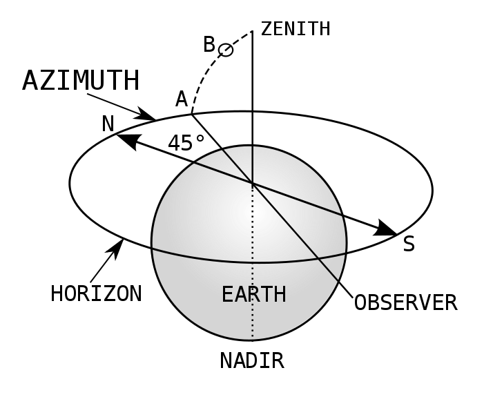
So in our ambisonic listening space, imagine you as an observer go to the origin and look due North (0 degrees). Then you turn 45 degrees East. This is the value of your Azimuth (position A in the image). You then tilt your head 45 degrees upwards. This is the value for your Elevation (position B).
So these two variables can describe any direction in a soundfield from an origin. What this can't seem to describe is how far away the object is. You could be looking straight at it but there's no variable to tell you whether it's on the moon or right in front of your nose.
Loudspeaker Orientation - but not Position
The ambi.decode~ help patch shows the horizontal coordinate system in action. Each output channel from the decoder is by convention assigned a loudspeaker position related to a platonic solid. For example with 8 channels you could choose a 2D horizontal 'ring' layout (octagonal), a 3D 'cube' layout, or a 3D 'superimposed tetrahedron' layout. The loudspeakers are then positioned in the listening space where the intersections occur between lines in the shape.
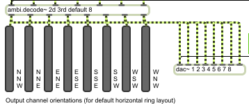
Depending on the chosen layout you can then feed decoder orientation values for each loudspeaker, as horizontal coordinate system pairs. The ambi.decode~ help patch has some examples:
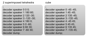
If you sketch out the example values (as I have), you can see how they work, along with predefined positioning, to construct a listening environment:
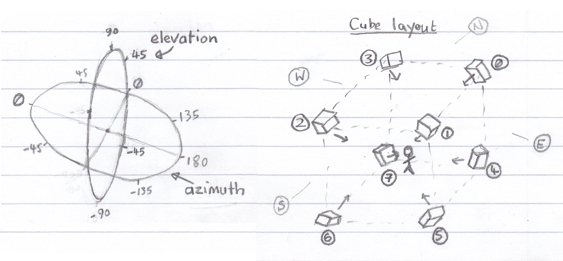
Looking at the cube layout sketch, you start to really get a sense of what an ambisonic soundfield really is. It's a 2 or 3-dimensional version of stereo (stereo being 1-dimensional). This also starts to explain why only the rotate transformation is included in Graham's patch. The other transformations make less sense in this context, and much more sense in the cartesian coordinate systems I'm used to.
The Sweet Spot
Ambisonics is therefore designed with a 'sweet spot' in mind. This spot will emanate from the origin, and it's size will be dependent on the loudspeaker setup and the nature of the listening environment (outside noise etc).

Looking for more information, I came across an introduction written by Florian Hollerweger, a Sound Art PhD student at Queen's University Belfast.
The text describes how there are two different approaches to decoding B-Format data (Projection vs. Pseudoinverse). However, both methods share a crucial feature in common - it's very important that the layout of the soundfield be as regular as possible - and as closely related as possible to a platonic solid shape which the decoder is instructed to decode for.
Higher-Order Ambisonics
Florian goes on to describe the nature of higher-order ambisonics. It quickly becomes clear that each higher order of ambisonics is basically about increasing the number of decoded channels - i.e. using a platonic solid with more intersections (to place the loudspeakers on).
This does a number of things:
- First, it increases the 'resolution' of loudspeakers, and therefore the 'localisation' of sounds. What 'localisation' means is your ability to point confidently to where you think a sound is coming from, without necessarily pointing straight to a loudspeaker. In other words, it's the illusion that the sounds around you are really floating freely rather than emanating from loudspeakers. This only applies for a listener in the sweet spot - degradation will still occur in a similar way as you move away from the sweet spot regardless of which order of ambisonics you use.
- However, secondly it will increase the size of the sweet spot. More speakers equals more volume, and the added loudspeakers mean that you can move them all further away to attain the same volume for a listener at the origin. The listener would have to walk further away from the origin before they experience the degradation - but the degradation would occur in a similar way.
- Ofcourse, it means adding a number more encoder channels - 5 more for second-order and 7 for third-order.
What Ambisonics Can't Do
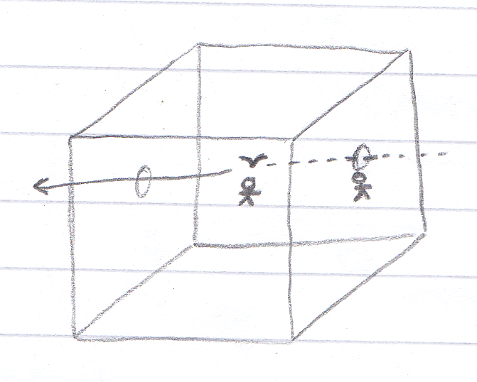
All of the emphasis in ambisonics is on the sweet spot. It's still that thing of imagining a single listener in the middle (like my stick man in the image above), or a collection of listeners in a single space hearing the same thing. Even with all the extra layers and complexity, it's still about creating one sound (or soundspace).
It's patently not about creating a number of different sound experiences at once, with a freely moving audience, all experiencing their own personal version of the sound. And, (as a specialised version of that), it can't produce an 'environmental' type of 3D sound.
What do I mean by that? Imagine a real physical bird flying through a 'cube' listening space, creating a fairly continuous noise as it flaps it's wings and crows. Imagine also that you are standing right next the point of the bird's entry, underneath a loudspeaker, looking toward the centre of the listening space. As the bird flies over your head you should hear the sound very loudly. The sound would then diminish for you even before the bird reached the centre of the space.
For a listener at the centre, the sound would start quietly and get louder when the bird reached the centre. This effect is not possible with ambisonics - you could cater for the listener at the centre (the sweet spot) but not for the listener at the edge. The soundfield is focused inwards, to a core audience.
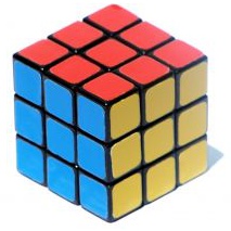
This 'environmental' effect would require a different geometry to those available in ambisonics - i.e. more of a grid than a platonic cube. Like a rubik's cube, with each intersection between each mini-cube furnished with loudspeakers. Ofcourse this in turn would require a different type of decoder.
Jaaga
The Jaaga building is modular, and large, and we have a maximum of 16 permanent loudspeakers for the building - some of which vary considerably in frequency range. The loudspeakers need to some extent to be distributed across the rooms, so one option would be to take 8 loudspeakers and set up an ambisonic room.
However the effect I'd like to achieve here would be the more environmental type - and specifically designed for a freely moving audience. We already have an irregular loudspeaker layout which takes into account various requirements:
- A clear sound environment for the large hall (downstairs) which can be useful for talks and screenings.
- Two loudspeakers for the Jaagaad installation on the first floor.
I don't want to force loudspeakers in the space to conform to a platonic solid. A geometry might be good, but rather one that is far more irregular (and explorable, and that relates somehow to the space).
Another option could be to develop a simple patch that combines a point from a 3D cartesian coordinate system with each mono sound. As the point associated with a mono sound closes in on a loudspeaker, the volume of that sound in that loudspeaker channel increases. Inspired by but different to ambisonics.
My next step could be to prototype this in Max/MSP and see how it works. But not to get too far ahead without considering the obvious: Who else has done this before, and what were their results?